Chinese wholesale Remote Control Intelligent Load Bank - 200kW Resistive Load Bank Air Cooled Single Phase Load Test – Gff Keypower
Chinese wholesale Remote Control Intelligent Load Bank - 200kW Resistive Load Bank Air Cooled Single Phase Load Test – Gff Keypower Detail:

|
KEYPOWER GENERATOR TESTER SPECIFICATIONS |
|||||
|
Measurement |
Range |
Accuracy |
Resolution |
Overload |
|
|
Voltage (V) |
10.0~500.0V |
± (0.4% reading+0.1%range) |
0.1V |
600V |
|
|
Current (A) |
0.030~5.000A |
± (0.4% reading+0.1%range) |
0.001A |
6A |
|
|
Power |
According to volt range & current range |
Power factor =1.0 |
<200W 0.1W |
|
|
|
± (0.4% reading+0.1% range) |
≥200W 1W |
||||
|
Power factor =0.5 |
≥2kW 10W |
||||
|
± (0.8% reading+0.2% range) |
|
||||
|
Power Factor |
0.20~1.00 |
±0.02 |
0.001 |
|
|
|
Frequency |
45~65Hz |
±0.2Hz |
0.01Hz |
|
|
|
Running Time |
99h59m |
±2min/hour |
1 minute |
|
|
|
Energy |
99999kWh |
Power factor= 1.0 |
0.001kwh |
|
|
|
± (0.4% reading+0.1% range) |
|||||
|
Power factor=0.5 |
|||||
|
± (0.8% reading+0.2% range) |
|||||
|
Harmonic Analysis (%) |
2-50 times and total harmonic |
|
|
|
|
|
Models You Can Choose |
|||||||||
|
Model |
Testing capacity |
Type of load |
Duty |
Cooling system |
Phase |
Rated Testing Voltage |
Rated Frequency |
Dimensions (L*W*H) (mm) |
Weight (kg) |
|
KPLB-100 |
0 - 100 kw |
Resistive or Reactive, PF = 1.0 or 0.8 |
Continuous |
Industrial grade axial fan |
Available at both single and three phase |
110-480 VAC |
50/60 Hz |
960*1060*1400 |
350 |
|
KPLB-200 |
0 - 200 kw |
1560*1310*1650 |
837 |
||||||
|
KPLB-300 |
0 - 300 kw |
1690*1440*1750 |
1083 |
||||||
|
KPLB-400 |
0 - 400 kw |
1900*1600*1900 |
1200 |
||||||
|
KPLB-500 |
0 - 500 kw |
1900*1600*1900 |
1400 |
||||||
|
KPLB-600 |
0 - 600 kw |
2100*1730*2000 |
1550 |
||||||
|
KPLB-700 |
0 - 700 kw |
2100*1730*2000 |
1650 |
||||||
|
KPLB-800 |
0 - 800 kw |
2400*2330*2100 |
1750 |
||||||
|
KPLB-1000 |
0 - 1000 kw |
2400*2330*2200 |
2150 |
||||||
|
KPLB-2000 |
0 - 2000 kw |
20 ft container |
6000 |
||||||
|
KPLB-5000 |
0 - 5000 kw |
40HC container |
16000 |
||||||
KEYPOWER Load Bank Technical Specifications
1. Resistive type of load, PF = 1.0. Stainless steel sheathed elements manufactured from high grade nickel-chromium alloys resistive wire covered by 3-year warranty.
2. Rated testing voltage: AC 3P4W, 110-480 VAC 50/60HZ.
3. Cooling mode: forced air-cooled, fans mounted on the side of the load bank blow horizontally. External utility power or internal tested power supply for fans.
4. Working mode: load step control
Total testing capacity ranges from 0kw to the max consisting of 10kw, 20kw, 50kw, 100kw load setting switches plus a 0-10kw fine-tuning knob. From 0kw to the max, any load combination is achievable. Load step resolution is 10kw.
5. Load bank features world-famous components to ensure reliable performance and longer service life including:
 contactors.
 switches, knobs and indicators.
 circuit breakers.
 intermediate relays.
 terminal blocks.
6. Parameter measuring accuracy grade: 0.5.
7. Load control accuracy: ±3%.
8. Load bank protections: over heating protection, cooling fans failure protection and over load protection with alarm.
9. Control mode: two control modes available: a) Local manual control; b) Optional: Manual control via a remote control panel (max control distance is 20m).
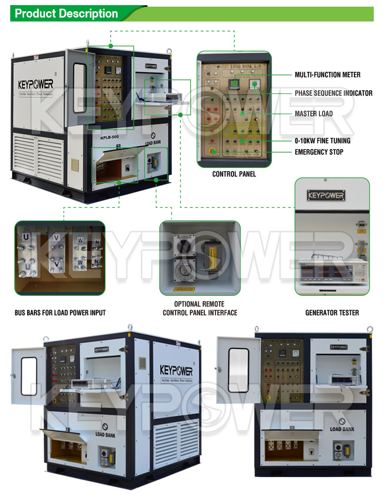
10. Parameter display and measurement: Control panel contains a  Multifunction Electricity Meter displaying voltage, current, load power, reactive power, apparent power, power factor, frequency etc. (Optional: a professional generator tester displays and measures all sorts of steady, dynamic parameters as well as harmonic wave, can be connected to a PC for data recording and test report printing).
11. Operating environment: Altitude: ≤1000m above sea level. Ambient temp: -10℃~+40℃ Relative humidity: ≤80% ventilated environment without explosive or corrosive dust. Not allowed to use in rainy outdoor environment.
Product detail pictures:


Related Product Guide:
Our development depends on the advanced equipment, excellent talents and continuously strengthened technology forces for Chinese wholesale Remote Control Intelligent Load Bank - 200kW Resistive Load Bank Air Cooled Single Phase Load Test – Gff Keypower , The product will supply to all over the world, such as: El Salvador, Accra, Serbia, we've got all day online sales to make sure the pre-sale and after-sale service in time. With all these supports, we can serve every customer with quality product and timely shipping with highly responsibility. Being a young growing company, we might not the best, but we are trying our best to be your good partner.
Products and services are very good, our leader is very satisfied with this procurement, it is better than we expected,


